


Installing DCC+Sound in the
American Models 4-6-2 PRR K-4
by
Michael Greene
** THIS PAGE IS INCOMPLETE AND STILL BEING FINISHED **
Please be patient - there are 15 pictures on this page to load for viewing!
The Pensylvannia K-4 streamlined Pacific (4-6-2) ) from American Models is striking when you see it running. In order to get it ready for running at an upcoming train show, I decided to install a SoundTraxx Tsunami (Medium Steam) decoder in it. Although this installation was not particularly difficult, it does require some planning due to the wiring that needs to be accomplished to provide for control of both the smoke unit and the synchronization of the chuff sound to the smoke unit. I encourage extra care in handling this model so that you don't mar the beautiful paint job.
from American Models is striking when you see it running. In order to get it ready for running at an upcoming train show, I decided to install a SoundTraxx Tsunami (Medium Steam) decoder in it. Although this installation was not particularly difficult, it does require some planning due to the wiring that needs to be accomplished to provide for control of both the smoke unit and the synchronization of the chuff sound to the smoke unit. I encourage extra care in handling this model so that you don't mar the beautiful paint job.
Note that throughout this article you can click on the the thumbnail of any picture and see a larger view.
) We started this project by opening the tender and the locomotive to examine how it was currently wired. The tender shell is easily removed by removing two screws on the bottom, and then carefully spreading the sides of the tender shell so the tabs are disengaged. With the shell off to the side, now carefully remove the cable tie that is bundling the extra wire. You will see that American Models wired power pickups on both trucks (very nice!), and then soldered those pickups (the two left pickups, and then the two right pickups) together where the shrink tubing is located. And from these solder points they continued to two wires from each solder point to the plug that connects to the locomotive. One pair of wires on the plug is used for the motor and the smoke unit (this is the inside pair), and one pair (the outside wire on each side of the plug) is used for powering the front headlight. We'll coming back to the wiring later in the article as we plan out the new wiring diagram.
We started this project by opening the tender and the locomotive to examine how it was currently wired. The tender shell is easily removed by removing two screws on the bottom, and then carefully spreading the sides of the tender shell so the tabs are disengaged. With the shell off to the side, now carefully remove the cable tie that is bundling the extra wire. You will see that American Models wired power pickups on both trucks (very nice!), and then soldered those pickups (the two left pickups, and then the two right pickups) together where the shrink tubing is located. And from these solder points they continued to two wires from each solder point to the plug that connects to the locomotive. One pair of wires on the plug is used for the motor and the smoke unit (this is the inside pair), and one pair (the outside wire on each side of the plug) is used for powering the front headlight. We'll coming back to the wiring later in the article as we plan out the new wiring diagram.
)
) The next step is speaker slelection. Generally I like to use the largest speaker I can fit in the available space. In this case I selected an ICC/Intervox speaker - Manufacturer part # S15X25VA). I ordered a number of these speakers a few years ago, but ICC/Intervox speakers are still available from various suppliers, including Allied Electronics. The datasheet for this speaker can be viewed on Allied Electronics' web site. As you can see from this picture this is a nice choice to fit right in the enter of the tender.
The next step is speaker slelection. Generally I like to use the largest speaker I can fit in the available space. In this case I selected an ICC/Intervox speaker - Manufacturer part # S15X25VA). I ordered a number of these speakers a few years ago, but ICC/Intervox speakers are still available from various suppliers, including Allied Electronics. The datasheet for this speaker can be viewed on Allied Electronics' web site. As you can see from this picture this is a nice choice to fit right in the enter of the tender. ) I oriented mine facing down as American Models has already provided a hole for sound exit, and I used the entire tender shell as the speaker enclosure. To make it easy to remove the speaker in the future if necessary, I used quick disconnect plugs on the Tsunami speaker wires (purple wires). Given the small size of the speaker wires, I did solder the the wire to the plugs instead of just crimping them. Once you have this done this would be a very good time to test your decoder before installing it to be sure there are no problems prior to installation. To make decoder testing easier, I use a Loy's Toys DCC Decoder Tester, but there are several options for such a jig to make decoder testing easier. Visit our Tips and Tools page using the left side menu button to find more about available decoder testers.
I oriented mine facing down as American Models has already provided a hole for sound exit, and I used the entire tender shell as the speaker enclosure. To make it easy to remove the speaker in the future if necessary, I used quick disconnect plugs on the Tsunami speaker wires (purple wires). Given the small size of the speaker wires, I did solder the the wire to the plugs instead of just crimping them. Once you have this done this would be a very good time to test your decoder before installing it to be sure there are no problems prior to installation. To make decoder testing easier, I use a Loy's Toys DCC Decoder Tester, but there are several options for such a jig to make decoder testing easier. Visit our Tips and Tools page using the left side menu button to find more about available decoder testers.
As I planned the revised wiring diagram for the locomotive, there were a few other considerations:
-
In addition to the motor and the front light, I wanted the smoke unit to be under function control.
-
I wanted the slide switch on the locomotive to continue to provide absolute control as to whether the smoke unit was on or off.
-
I also wanted a visual indicator as to whether the smoke unit was on or off
-
The Tsunami provides a single wire to connect to a cam for synchronization of the chuff sound. The use of this wire is optional -- the decoder comes with auto-chuff enabled, and the signal on the cam wire is ignored. However I wanted better synchronization of the sound with the smoke unit, and thus I needed to wire it in as well.
After reviewing the Tsunami installation documentation, I decided to connect the smoke unit in with the forward light on function zero - F0(F). This would provide a visual indicator -- if the forward light is on, then the smoke unit is powered, subject to the override of the slide switch on the rear of the locomotive. However the smoke unit draws more current that the function wire can provide. To address this issue, I installed a relay such that F0(F) will control the relay, and this more current directly from track power could be provided directly to the smoke unit via the relay.
Here is the wiring diagram (to be posted shortly). I should note that unlike my earlier American Models USRA Pacifics, the wiring colors in this locomotive had been colored black to make them less visually noticeable. However they are uniquely colored, and you may need to remove some of the black compound from the wiring INSIDE the tender in order to connect the appropriate colors.
As per the wiring diagram, I made the following wiring connections and/or changes:
-
The connection of the Tsunami speaker wires as previously described to quick disconnect plugs; After installaing the quick disconnect plugs, I did not connect them to the speaker. I'll leave that until near the end of the process.
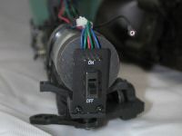 As the next step I did some re-wiring of the small board containing a sub-miniature slide switch. This switch controls whether or not power is supplied to the smoke unit. The board is installed in the cab area of the locomotive. The picture at the right shows the board after the shell has been removed. In order to make this re-wiring easier, I removed the two screws (near of the bottom of the board) that secure it to the chassis frame.
)
) |
|
) |
|
) |
) |
) |
) |
) |
|
) |
) |
Copyright © 2002-2007, C. M. Greene. All rights reserved.
webmaster