


Using Your F-3 A/B with S Helper Service's DCC Sound Decoder
(Please be a bit patient -- there are six pictures to load at the bottom of the page. Thanks.)
S Helper Service is the first S scale manufacturer to offer a DCC equipped locomotive, and the first American manufacturer in any scale to offer a locomotive equipped with DCC controlled lights & sound directly from the manufacturer. Another first for S scale! S Helper Service partnered with SoundTraxx, the leading manufacturer of DCC sound decoders, to bring us a locomotive that is pre-wired with DCC controlled lights and sounds, ready to run!
Installation
If you received your F-3's without the DCC Sound decoder installed at the factory, you'll need to perform the installation before starting. Installation is very simple - no soldering or special wiring is required - S Helper Service has everything on a simple plug. Just remove the cover on the F-3 A unit, remove any AC sound unit or DC shorting plug that is installed, and plug in your DCC sound decoder. It's that simple. For those a bit nervous, Appendix A describes the installation process with photos. The B unit is also controlled by the DCC decoder in the A unit. See note 1 below for more information on connecting the B unit.
Getting Started
Once the DCC sound decoder is installed, you are ready to start running the locomotive(s).
CAUTION! Before you put your locomotive on the DCC controlled layout, make sure that the DCC system is set to deliver 16V or less to the layout. On most systems this corresponds to N, HO, or NORMAL settings as labeled by the DCC system manufacturer. DO NOT use this decoder on any layout that is set to O or G settings or is set to deliver more than 16V to the track!
Because the locomotive was designed to be factory equipped with DCC controlled lights & sound, no additional wiring is required for either sound or control of the headlight, MARS light and number boards. When you put you locomotive on the track, it will be pre-programmed at address 3. You can easily change the address using your DCC system. In addition to the address, these functions are already set up:
|
F0 |
Turn on & off headlight |
|
F1 |
Turn on & off bell |
|
F2 |
Turn on & off horn |
|
F3 |
Not assigned |
|
F4 |
Turn on & off dynamic brakes |
|
F5 |
Turn on & off number board lights |
|
F6 |
Turn on & off the Hyperlight effect (MARS) (if your locomotive has one) |
|
F7 |
Set dim or bright headlight |
|
F8 |
Mute sound |
So put your locomotive on the DCC layout and start running. Select address 3 and give it a try - you'll be impressed at how easy it is to control the locomotive and special effects. Some DCC systems require that you take some action to identify whether the decoder has 14,28, or 128 speed steps. The DCC decoder comes pre-programmed for 28/128 speed steps. Set it to 128 if that option is available, otherwise set it to 28. You'll also notice at that the decoder is pre-programmed to ramp the engine RPMs sound as the locomotive begins to move. Try out the functions above to see all the special effects that are built right in.
Of course that is not all. The programmable features of the DCC sound decoder make its operating characteristics highly customizable. Every thing from speed curves to selection of three different horns, changing which function controls a particular special effect, selecting the second headlight (Hyperlight) special effect (MARS, Gyralite, single strobe, etc.), setting up the headlight for Rule 17 operation and changing the volume of the various sounds. The DCC sound decoder also supports consisting, and numerous other features. Consult the DCC owner's manual enclosed with your locomotive or decoder for additional information on tailoring the locomotive to fit your needs.
Additional Notes, Hints & Tips
- If you are planning to control the B unit with the decoder that is installed in the A unit, make sure you do
NOT have a DC shorting plug in the B unit. We strongly recommend that you either remove the shell and verify this,
or put it on a section of track controlled by a DC power pack and test it (it
should not move). You will likely have a "smoking" decoder if you accidentally
connect up a B unit that has a shorting plug installed, and smoking decoders
do not run! After you have verified
that a DC shorting plug is not installed in the B unit, then just connect the supplied MU cables from the A unit to the B unit, making sure not to cross the cables between the A and B unit. In this configuration the A-B set is treated as a single address on your DCC system.
-
The B unit is also factory-ready for its own DCC sound decoder, in case you want to have separate control of the B unit. All you need to do is purchase a second DCC sound decoder, remove the cover, and plug it in. Now you'll have independent control of each locomotive on your layout, and of course double the sound! To order another DCC sound decoder, simply contact either your dealer or S Helper Service directly (1-800-465-0303 or via the web site at http://www.showcaseline.com)
and order S Helper Service part number 00745
($159.95 each with wiring harness).
- For Lenz Set-01 users, we recommend that you make sure your command station and LH100 throttles have been upgraded to Version 3. Version 3 gives you access to 4 digit locomotive addresses and all eight functions. Please contact your Lenz dealer or Lenz Electronics directly. Their web site is http://www.lenz.com or you can e-mail them at support@lenz.com.
-
Some users of early NCE Powerhouse Pro DCC systems may see a situation where the DCC equipped locomotive runs fine on their layout. But when the B unit is connected via the MU cables and the user attempts to run the locomotive, the booster shuts down and reports an overload or short condition via the front panel LED on the Powerhouse Pro. If this occurs please contact NCE for a chip upgrade for your Powerhouse Pro. It seems that on some older systems, the power station was especially sensitive to shorts,
and when some SoundTraxx decoders are placed on the layout, the capacitors that are charging on the decoder look like a short to the Powerhouse Pro. NCE has already found and fixed that problem, and has a chip upgrade available to you if you find this situation. NCE can be reached via their web site at http://www.ncedcc.com or via phone at 1-716-671-0370 (9am-4pm ET).
-
At the factory setting (mid-range) of the horn volume, the decoder delivers a crisp 105-110 decibels of sound! Imagine the sounds from your layout with several DCC sound equipped F-3s running on the layout simultaneously. Fortunately the decoder allows you to customize the volume of each of the sounds, for those who are overwhelmed.
- As the locomotive comes from the factory, F0 controls the top headlight. If your locomotive includes a second light right below it (for a MARS light, etc.), this is controlled by F6. On some railroads, standard practice was to put the MARS light on top, and the standard headlight in the lower headlight casing. Once again it appears that excellent engineering from S Helper Service makes this easy. Here's what you do:
- Remove the A unit shell (4 screws on the bottom of the loco).
- Remove the two screws that hold the cab floor in place (Between the engineer and the fireman) You can see these screws in the center of the cab floor if you look at the photo in Step 4 of Appendix A, the Installation instructions, further down this page.
- Underneath the cab floor on each side you will see two 2-pin connectors. The connections on one side go to both headlights, and the connections on the other side go to the number boards. Swap the two connections on the side where the wires go to the headlights. This was on the fireman side on my loco, and I expect yours. Please note that the connectors are NOT "keyed". So be sure when you reconnect them, that the red wire connects to the red wire and the white wire connects to the white wire. Also you will note that S Helper Service has a small piece of tape on each of the connectors. I recommend replacing it when you're finished, as it will keep the connections from separating accidentally.
- All done. Replace the screws that hold the cab floor in place and then replace the shell.
This should work for all the environments where you separate control of the headlight and MARS light.
- In the case where the DCC decoder is installed, by default Function 0 (F0) controls the upper headlight and Function 6 (F6) controls the lower headlight. If you swap the connectors as described above, now F0 will control lower light and F6 the upper light. In addition to changing the location of the MARS light, the DCC decoder makes changing the light effect for the headlight (Function 0(F0)) and/or the MARS light(F6) very easy. There is a configuration variable (CV) that can be programmed to your choice of values. For example if you want F6 to turn on a Gyralite instead of a MARS light, simply change the value of CV52 from 2 to 3. All set. See the manual that came with your S Helper Service DCC Decoder for more information. Some of the options are:
- on/off light
- dimmable light (using F7 as the dimmer control) (default for F0)
- MARS light (default for F6)
- Gyralite
- Oscillating headlight
- Single flash strobe
- double flash strobe
- D312 rotary beacon
- Prime Stratolite
Appendix A - Installation
If you need to install your DCC sound decoder, it is very easy to do. Just follow these simple steps. Pictures are include to assist your work..
- Turn the A unit upside down. We recommend the use of a foam cradle, but if you don't have one of these use something soft, so you don't damage or break off the horns on the top of the locomotive.
- Remove the four Philips screws -- two at each end of the underside
of the locomotive.
gal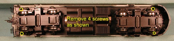
- Now you can turn the locomotive right side up, and remove the shell. If this is the first time the shell is removed it may be a little tight. On one of my locomotives I found it helped to remove the pilot. There are two screws on bottom of the nose that hold the pilot in place. Also remember to be careful with the rear of the loco shell to avoid damaging the "hoses". Another approach that may help is to insert a screwdriver through the sprung rear door on the locomotive and carefully press down on the frame.
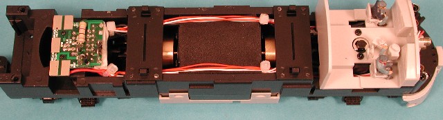
- With the shell off, remove any AC/DC Sound Unit or DC Shorting plug
that is in place. In this next photo you can see the inside of the
locomotive with only the DC shorting plug installed.
And this next photo is a close-up of the F-3 socket, as it would appear with the DC shorting plug or AC/DC sound board removed. Notice that the socket has two rows of holes, one of which is longer than the other. This insures that when you put the wiring harness plug in, it will be oriented the correct way.
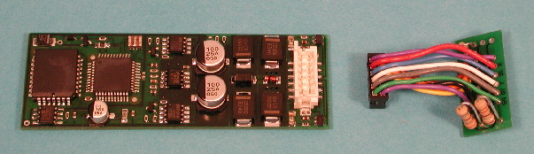
- Now prepare your DCC sound decoder. In the next photo you will notice
two parts: the decoder with a socket, and a wiring harness. (For those
who are curious, the decoder is 1.1" W x 3.25" L.) One end
of the harness plugs into the decoder (it should be obvious). Plug it
in, and make sure it is all the way in.
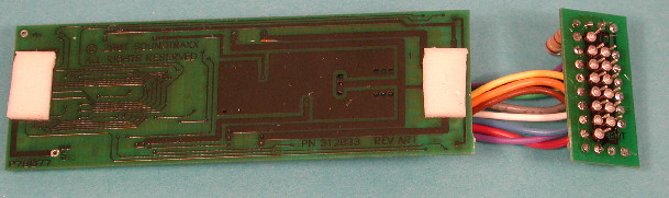
- The decoder will be installed on the locomotive frame, so that the
component side faces the inside top of the shell. In order to keep it
from moving around, I placed two small pieces of double sided foam tape
on the underside of the decoder (the side without components).Remove
only one side of the tape, so that you can stick it to the decoder.
The other side will be removed when you are ready to place it in the
loco.
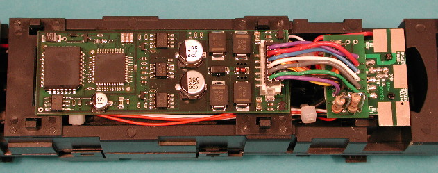
- Now plug the end of the wiring harness not connected to the decoder,
into the socket provided on the F-3. Be careful to make sure all the
pins on the plug are aligned with a hole in the socket. Here is a picture
of it installed.
When you have the plug in place, press it fully into the socket. Once it is all the way in, you can remove the other side of the pieces of foam tape, and stick the decoder to the frame. The speaker is in the top of the shell, and will be automatically connected when the shell is replaced. - Now you're ready to put the shell back on. Then replace the four screws (and the pilot and two screws for it if you removed them). The installation is complete. As always we recommend you test your installation by placing it on the programming track, and attempting to read or write a CV. CV1 (the Address CV) comes set at the factory to 3. So if you have a DCC system that allows you to read a CV, try to read CV1 and look for 3. You can change this to another value and test programming the decoder. Just remember what you set it to,so that when you take it to the layout, you will know what address to use.
- Enjoy!
Copyright © 2002-2006, C. M. Greene. All rights reserved.
webmaster