


Getting Started with the DCC Sound Decoder
in your S Helper Service F-7 A/B
Copyright © 2003, S Helper Service, Inc.
Revision 06/2003 D
Thank you for your purchase of a DCC equipped F-7 A/B from S Helper Service. S Helper Service is pleased to continue its pioneering efforts in S scale releasing a new plug & play DCC sound decoder for the F-7 locomotives. S Helper Service has partnered with SoundTraxx, the leading manufacturer of DCC sound decoders, to bring you a locomotive that is pre-wired with DCC controlled lights and sounds, ready to run!
Installation
If you received your F-7's without the DCC Sound decoder installed at the factory, you'll need to perform the installation before starting. Installation is very simple - no soldering or special wiring is required the DCC decoder itself plugs right into the socket in the F-7. Just remove the cover on the F-7 A unit, remove any AC sound unit or DC shorting plug that is installed, and plug in your DCC sound decoder. It's that simple. For those who are a bit nervous, Appendix A describes the installation process with photos. The B unit is controlled by the DCC decoder in the A unit. See note 1 below for more information on connecting the B unit.
Getting Started
Once the DCC sound decoder is installed, you are ready to start running the locomotive(s).
CAUTION! Before you put your locomotive on the DCC controlled layout, make sure that the DCC system is set to deliver 16V or less to the layout. On most systems this corresponds to N, HO, or NORMAL settings as labeled by the DCC system manufacturer. DO NOT use this decoder on any layout that is set to O or G settings or is set to deliver more than 16V to the track! Operating this DCC Sound Decoder on track voltages greater than 16V will void your warranty, generate excessive heat, and possibly permanently damage your decoder.
Because the locomotive was designed to be factory equipped with DCC controlled lights & sound, no additional wiring is required for either sound or control of the headlight, MARS light, number boards and classification lights. When you put you locomotive on the track, it will be pre-programmed at address 3. You can easily change the address using your DCC system. In addition to the address, these functions are already set up:
|
F0 |
Turn on & off headlight |
F5 |
Turn on & off the Hyperlight effect (MARS) (if your locomotive has one) |
|
F1 |
Turn on & off bell |
F6 |
Turn on & off red classification lights |
|
F2 |
Turn on & off horn |
F7 |
Turn on & off green classification lights |
|
F3 |
Turn on & off number board lights |
F8 |
Mute the sound |
|
F4 |
Turn on & off dynamic brakes |
|
|
So put your locomotive on the DCC layout and start running. Select address 3 and give it a try - you'll be impressed at how easy it is to control the locomotive and special effects. Some DCC systems require that you take some action to identify whether the decoder at a particular address has 14, 28, or 128 speed steps. The DCC decoder comes pre-programmed for 28/128 speed steps. Follow the procedures specified by your DCC system manufacturer to set the address of your decoder to 128 speed steps if that option is available, otherwise set it to 28. You'll also notice at that the decoder is pre-programmed to ramp up the engine RPMs sound through eight distinct notches as the engine is accelerated and ramp down as the engine begins to slow. Try out the functions above to see all the special effects that are built right in.
Of course that is not all -- the programmable features of the DCC sound decoder make its operating characteristics highly customizable. Everything from speed curves to selection of three different horns, changing which function controls a particular special effect, selecting the second headlight (Hyperlight) special effect (MARS, Gyralite, single strobe, etc.), setting up the headlight for Rule 17 operation and changing the volume of the various sounds can be modified. The DCC sound decoder also supports consisting, and numerous other features. Consult the DCC Decoder Owner's Manual enclosed with your locomotive or decoder for additional information on tailoring the locomotive to fit your needs.
Additional Notes, Hints, & Tips
- If you are planning to control the B unit with the
decoder that is installed in the A unit, make sure you do NOT have
a DC shorting plug in the B unit. We strongly recommend that you
either remove the shell and verify this, or put it on a section of
track controlled by a DC power pack and test it (it should not move).
You will likely have a "smoking" decoder if you accidentally
connect up a B unit that has a shorting plug installed, and smoking
decoders do not run! After you have verified that a DC shorting plug is
not installed in the B unit, then just connect the supplied MU cables from
the A unit to the B unit, making sure not to cross the cables between the
A and B unit. In this configuration the A-B set is treated as a single
address on your DCC system.
- In the event you want to have separate DCC control
and/or sound in the B unit, the B unit is also factory-ready for its own
DCC sound decoder and is factory-equipped with a speaker. All you need to
do is purchase a second DCC sound decoder, remove the cover, and plug it
in. Now you'll have independent control of each F-7 unit, and of course
double the sound! Remember to assign a unique address to the B unit
decoder, and you can create a multi-unit lashup (aka consist) with the A
unit if desired. To order another DCC sound decoder, contact either your
dealer or S Helper Service directly (1-800-465-0303 or via the web site at
http://www.showcaseline.com) and
order S Helper Service part number 01199 ($179.95 each). If you install a
decoder in the B unit, DO NOT use the MU cables between the A & B
units.
- For Lenz Set-01 users, we recommend that you make
sure your command station and LH100 throttles have been upgraded to
Version 3.5. Version 3.5 gives you access to 4 digit locomotive addresses,
up to thirteen functions, the ability to individually set F1-F8 as
non-latching which is key for sound decoder users, and many other new
features. Please contact your Lenz dealer or Lenz Electronics directly.
Their web site is http://www.lenz.com or
you can e-mail them at support@lenz.com,
or telephone them at 1-978-250-1494.
- Some users of early NCE Powerhouse Pro DCC systems
may see a situation where the DCC equipped locomotive runs fine on their
layout. But when the B unit is connected via the MU cables and the user
attempts to run the locomotive, the booster shuts down and reports an
overload or short condition via the front panel LED on the Powerhouse Pro.
If this occurs please contact NCE for a chip upgrade for your Powerhouse
Pro. It seems that on some older systems, the power station was especially
sensitive to shorts, and when some SoundTraxx decoders are placed on the
layout, the capacitors that are charging on the decoder look like a short
to the Powerhouse Pro. NCE has already found and fixed that problem, and
has a chip upgrade available to you if you find this situation. NCE can be
reached via their web site at http://www.ncedcc.com
or via telephone at 1-716-671-0370 (9am-4pm
ET).
- Users of some early model Digitrax Chief command stations (DCS100) may experience the situation where the motor, headlight, horn, bell, number board lights and dynamic brakes sounds work, but Functions 5, 6, 7 and 8 do not work. You can generally correct this situation for control of this decoder by programming a value of 4 into CV30. Since many new decoders support more than four functions, if you experience this situation you may also wish to contact Digitrax at some point about an upgrade for your Chief. If you do get your Chief upgraded, remember you may need to reset your decoder to remove the value of 4 in CV30.
- The decoder delivers good crisp sound at the mid-range
factory setting! For those who want either a little more or a little less
sound, you can customize the configuration of the decoder to alter the
volume of each of the sounds (up or down). See the decoder manual for more
information.
- As the locomotive comes from the factory, F0 controls the top headlight. If your locomotive includes a second light right below it (for a MARS light, etc.), this is controlled by F5. On some railroads, standard practice was to put the MARS light on top, and the standard headlight in the lower headlight casing. Making this change is very easy -- here's what you do:
- Remove the A unit shell (4 screws on the bottom of the loco).
- Remove the two screws that hold the cab floor in place (between the engineer and the fireman).
- Underneath the cab floor on each side you will see two 2-pin connectors. The connections on one side go to both headlights, and the connections on the other side go to the number boards. Swap the two connections on the side where the wires go to the headlights. This should be on the firemans side of your loco. Please note that the connectors are NOT "keyed". So be sure when you reconnect them, that the red wire connects to the red wire and the white wire connects to the white wire.
- All done. Replace the
screws that hold the cab floor in place and then replace the shell. This
should work for all the environments where there is both a headlight and MARS
light.
- In addition to changing the location of the MARS light as described in item 6
above, the DCC decoder makes changing the light effect for the headlight
(Function 0(F0)) and/or the MARS light (F5) very easy. There is a configuration
variable (CV) that can be programmed to your choice of values. For example if
you want F5 to turn on a Gyralite instead of a MARS light, simply change the
value of CV52 from 2 to 3. All set. See the technical manual that came with
your S Helper Service DCC Decoder for more information. Some of the options
are: on/off light, MARS light (default for F5), Gyralite, oscillating headlight,
single flash strobe, double flash strobe, D312 rotary beacon, and Prime
Stratolite.
Appendix A - Installation
If you need to install your DCC sound decoder, it is very easy to do. Just follow these simple steps. Pictures are included to assist your work.
- Turn the A unit upside down. We recommend the use of a foam cradle, but if you don't have one of these use something soft, so you don't damage or break off the horns on the top of the locomotive.
-
Remove the fourPhilips screws show in the photograph on the next page -- two at each end of the underside of the locomotive.
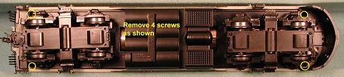
We recommend the use of a #0 screwdriver. (Wehave found that the #0x4-inch screwdriver made by General works well. Generals item number is 702, and the screwdriver is available from Walthers as item number 285-702.) Sometimes the screws are tight make sure the screwdriver engages the screw firmly to reduce the risk of stripping. - Now you can turn the locomotive right side up, and remove the shell. If this is the first time the shell is removed it may be
a little tight. Sometimes it may help to remove the pilot. There are two
screws on bottom of the nose that hold the pilot in place. Please take
care with the rear of the loco shell to avoid damaging the"hoses".
 Another approach that may help is to insert a screwdriver through the sprung rear door on the locomotive and carefully
press down on the frame.
Another approach that may help is to insert a screwdriver through the sprung rear door on the locomotive and carefully
press down on the frame.
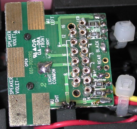
- With the shell off, remove any AC/DC Sound Unit or DC Shorting plug that is in place. The photo to the right is a close-up of
the F-7 socket, as it would appear without the DC shorting plug or with
the AC/DC sound board removed. Since the plug is on the decoder board, it
will obviously only fit in one direction and still allow you to put the
shell back on.
- Examine the decoder and you
will notice that the plug is on the bottom (non-component)
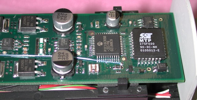 side of the
decoder. Orient the decoder in your hand so that the plug end of the
decoder aligns with the socket of the locomotive. Now slide the right end
of the decoder UNDER the two metal tabs as show in photo at the top of the
next page. DO NOT attempt to snap the board over the tabs, as the tabs are
metal (not plastic) and will not bend! You will need to slide the decoder
almost all the way to the back wall of the cab.
side of the
decoder. Orient the decoder in your hand so that the plug end of the
decoder aligns with the socket of the locomotive. Now slide the right end
of the decoder UNDER the two metal tabs as show in photo at the top of the
next page. DO NOT attempt to snap the board over the tabs, as the tabs are
metal (not plastic) and will not bend! You will need to slide the decoder
almost all the way to the back wall of the cab.
- No
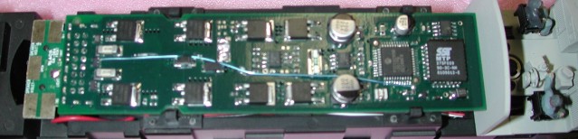 w while carefully watching the pins on the decoder plug, align them with the socket and press in. You will note that there
are two small cutouts in the decoder board where the other pair of metal
tabs are nearer the socket.
w while carefully watching the pins on the decoder plug, align them with the socket and press in. You will note that there
are two small cutouts in the decoder board where the other pair of metal
tabs are nearer the socket.
Enjoy!
Copyright © 2002-2006, C. M. Greene. All rights reserved.
webmaster